Wx100-ModbusGW#
1. Introduction#

Wx100-ModbusGW is a 2-in-1 Modbus device. For the price of a single low-cost unit, you effectively receive 2 devices:
- A wireless Modbus-TCP to Modbus-RTU converter gateway.
- A Modbus-TCP digital/analog I/O boards.
Best of all, both the gateway and the I/O functions are available simultaneously to the SCADA host or the IIoT client.
Built on the Wx100 super PLC platform, this device is supplied as a standalone, ready-made gateway device suitable for any SCADA or IIoT applications – no programming required!
Wx100-ModbusGW enables any legacy RS485 connected Modbus-RTU devices to instantly become Wireless Modbus-TCP server . All settings such as the serial port baud rate, WiFi SSID etc can be accomplished using the built-in keypad+OLED display, or from a PC or a smartphone.
1.1. Model Options#
There are two Wx100-ModbusGW options:
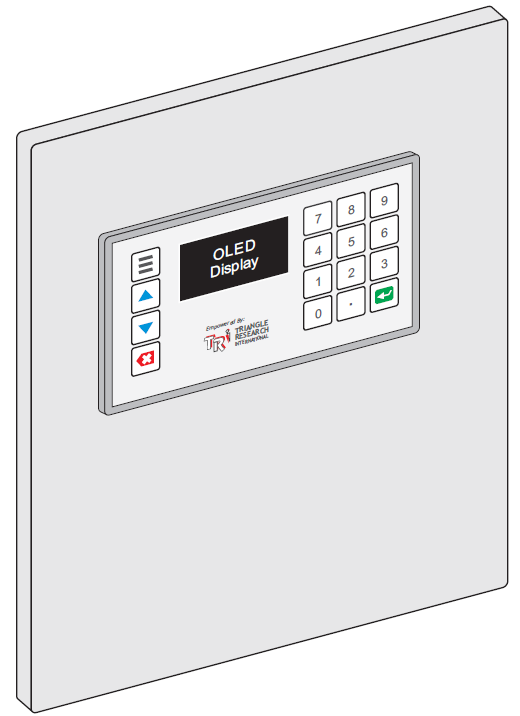
- Wx100-ModbusGW: This is a standard model with an internal antenna for the WiFi signal. The antenna is integrated on the module itself. It is designed mainly to be installed on exterior front cover of a control panel. It is not suitable to be installed inside a metallic control panel as the metal can block or greatly diminishes WiFi signal. Note that there is no option to add an external antenna to the standard Wx100-ModbusGW.
- Wx100-ExtA-ModbusGW: This model comes with an antenna cable and an external antenna as shown in the photo below. This gateway model can be installed inside a metallic control panel since the Wi-Fi signal will be captured by the external antenna and conduct via the antenna cable into the CPU. See Appendix A-3: Installing External Antenna for more details.
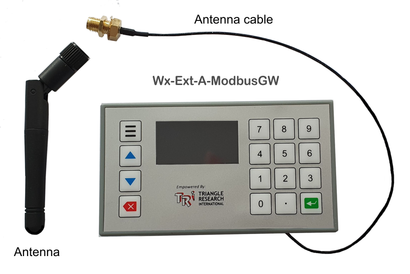
Note: Functionally, both Wx100-ModbusGW and Wx100-ExtA-ModbusGW are identical. The only difference is whether the antenna is integrated inside the unit or can be installed externally. So the model name: “Wx100-ModbusGW” throughout this document is applicable to either model.
2. How Does It Work?#
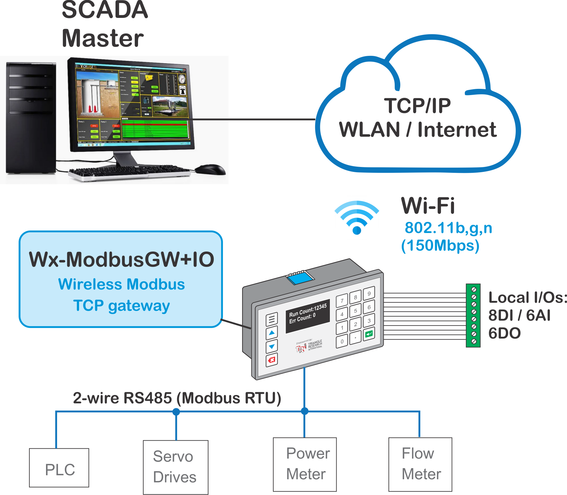
- A Modbus-TCP client, such as a SCADA host, can send Modbus-TCP command packets to the gateway via LAN or the Internet. The gateway will automatically convert the Modbus-TCP command packets it receives into Modbus RTU protocol and send out to its RS485 bus. Likewise, when the Modbus RTU device send a response packet, the gateway will convert the RTU response packet it receives into Modbus-TCP response packet and send out via the network router. Hence any Modbus-RTU device connected in parallel to the gateway’s RS485 port can be accessed from a single Wx100-ModbusGW device
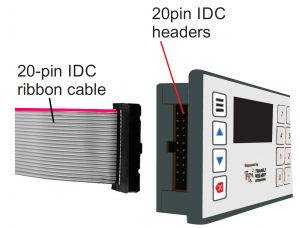
- Wx100-ModbusGW also provides industrial voltage level digital and analog I/Os on a 20-pin headers on its side that provides 8 digital inputs, 6 analog inputs and 6 digital outputs that can be directly read and written by the SCADA host. The I/O signals can be tapped using a simple 20p ribbon cable. Alternatively, an optional terminal board with screw terminals is available for purchase to facilitate quick wiring.
3. Product Specifications#
| WiFi & Modbus-TCP | |
| WiFi Frequency: Supported Types: WiFi Speed: Number of incoming connections: Supported Modbus functions: |
2.4GHz 802.11b, g, n @HT20 Up to 72Mbps >= 5 Function 01,02,03,04,05,06,15,16 |
| RS485 Serial Port | |
| Supported Baud Rates:Data & Stop Bits: Parity: |
2400,4800,9600,19.2K,38.4K, 62.5K,100K,115.2K and 230.4Kbps 7 or 8 data bits; 1 or 2 stop bits; Odd, Even or None |
| I/Os | |
| Input OFF voltage: Input ON voltage: Output OFF voltage: Output ON voltage: Output ON max current: |
<= 3VDC >= +5VDC Vp – 2V (Vp is the Power supply voltage) < 0.1V <=0.5A |
| Power Consumption | |
| Voltage (Recommended) Voltage (Min. & Max) Current: |
12 to 24VDC 9V & 30VDC 50mA @24VDC |
4. Installation & Wiring#
The Wx100-ModbusGW is flexible and can be installed on the front cover of any industrial enclosure. It can also be installed readily on a DIN rail or using just screws, nuts and PCB standoffs. Please refer to Appendix A for detailed illustration on the various options for installing the Wx100-ModbusGW.
4.1 ModbusTCP Gateway Wiring
If you are only using Wx100-ModbusGW as a gateway and not using its I/O function, then wiring is really simple. You only need to connect a regulated, 12 to 24V DC (maximum 30V) power supply to the +/- power supply terminals and a two-wire RS485 cable to the +/- terminal of RS485 connector, as shown below:
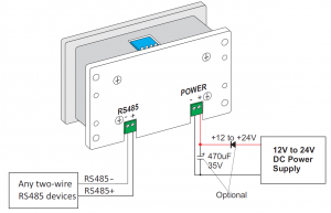
If desired you can also cover up the unused I/O header pins using the silicone dust cover supplied with the product after installation of the Wx100-ModbusGW to protect the pins against accidental short circuiting.
4.2 Wiring to The I/O Pins
Wx100-ModbusGW features 14 industrial voltage level digital and analog I/Os (see I/O specifications in Section 3) on a 20pin, 0.1″ pitch IDC header that can be read/written directly by the Modbus client.
For absolute lowest cost you can simply make a matching ribbon cable with a 0.1″ pitch IDC connector and tap the signals directly from the wires. The I/O signals are located on the header pins as shown below
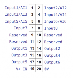
(Note you can ignore pin 19 and 20 as these two are alternative pins to supply power to the Wx100-ModbusGW module and they are not needed if you have already wired the power directly to the modules’ power supply screw terminals).
4.3 Wiring Using Optional Wx-TERM8
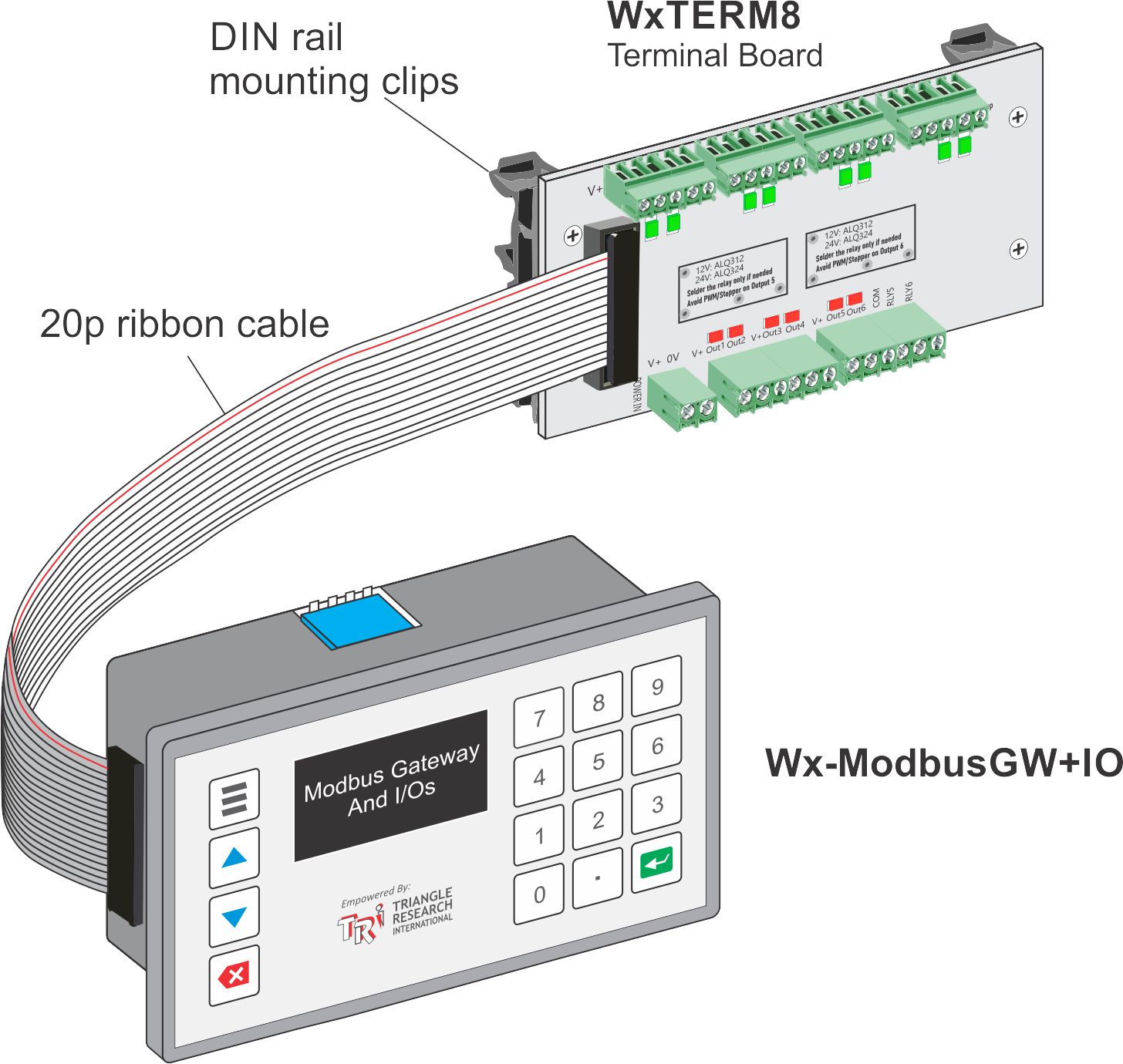
However, for more professional installation we recommend purchasing an optional Wx-TERM8 board which includes a connecting ribbon cable, a PCB that provides LED indicators for digital i/os and screw terminals to simplify wiring to your field sensors or actuators, as shown below:
5. Configuring Wi-Fi#
The Wx100-ModbusGW connects to the TCP/IP network via Wi-Fi. Hence the first thing that you need to do is to configure the device using the known SSID of the Wi-Fi network in order to connect to it to perform its function.
The Wx100-ModbusGW has a built-in keypad and an OLED display which makes it very convenient to configure the Wi-Fi parameters without any other tools. However, It is also handy if you prefer to configure it use your Smartphone or PC with the help of the built-in web App.
5.1 Setup WiFi Using Keypad & Display#
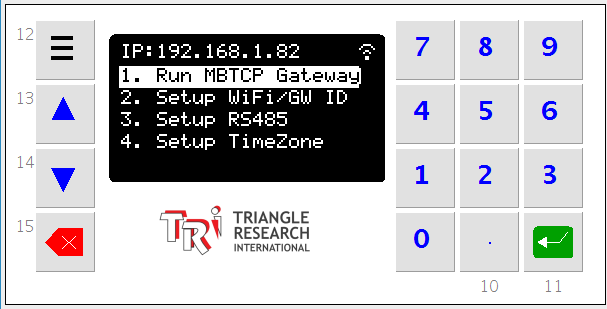
1. First, connect power to the device as per described in Section 42. Once power on, the Wx100-ModbusGW will attempt to connect to a factory default SSID. Since it won’t find that SSID after 50 re-tries it will give up and report “No WiFi Connect”. At any time you can then press the menu button (3-bar) on the keypad and a menu will appear on the OLED screen as follow:
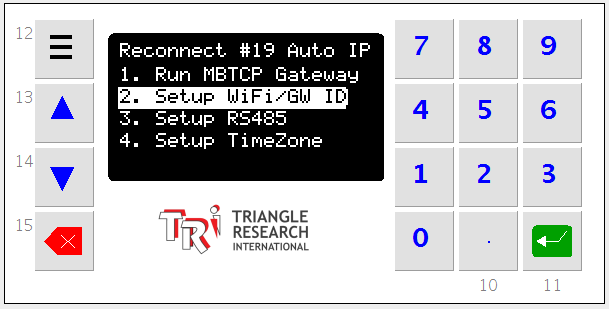
3. Select the item “2. Setup WiFi/GW ID” and press the green “Enter” key. Another menu will show up, allowing you to select configuration of the WiFi SSID, the WiFi Passkey.
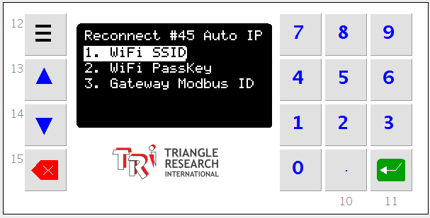
4. Due to small screen size only 10 alphanumeric keys are displayed at a time. To select a character, press the 0 to 9 numeric key on the keypad . For example if you press the “1” key on the following keypad the character “B” will be entered.
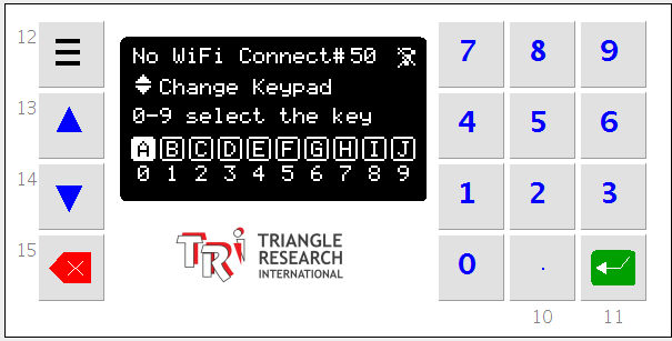
5. By pressing the <up/down> arrow keys you can switch the keyboard to another set of alphanumeric characters. For example pressing ‘9’ key and then the ‘7’ key in the following character set will enter “TR”
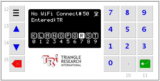
6. Enter one character at a time, all the characters of the SSID of the WiFi network that the Wx100-ModbusGW is to be connected to . If you have entered a wrong character, press the red “Backspace” key to delete the last entered character. When all the characters have been entered, press the green “Enter” key to save the new SSID to the Wx100-ModbusGW.
7. You will then be offered the choice to save the SSID, to reboot the Wx100-ModbusGW with the new SSID (provided you have already entered the correct Passkey) , or to abort the new SSID you just entered.
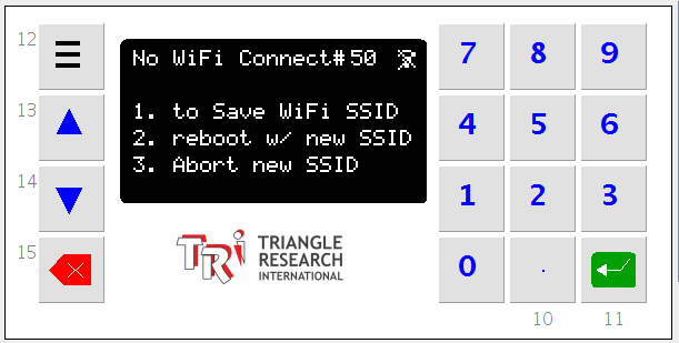
8. Press “1” key to save the new SSID you have entered. You will then be brought back to previous menu and you can then do the same for WiFi Passkey (aka WPA or WPA2 password).
9. Once you have setup both the WiFi SSID and Wi-Fi Passkey, please turn off the power to Wx100-ModbusGW, wait 5 seconds and turn power back on. The newly saved SSID and WiFi security key will only take effect after the device has been rebooted.
10. If the SSID and Passkey have been correctly entered, the device should connect to your router within a few seconds after power up. The IP address assigned by the network router will be displayed on the very first line on the screen. This is the IP address of the Modbus Gateway and Modbus I/O card that your Modbus client program (such as the SCADA master) will need to deal with.
11. If the device could not connect to the router, please check the following:
- SSID and Passkey are typically case sensitive so make sure that they have been correctly entered.
- The SSID you entered is for the 2.4GHz WiFi band only.
5.2 Setup Wi-Fi Using Soft AP Mode#
- Remove the DIP Switch dust cover (refer to section 1.10) and turn ON DIP switch #3 on the Wx100-ModbusGW.
- Power cycle the device.
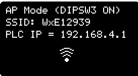
- Once power up with DIP switch #3 turned ON, the Wx100-ModbusGW will setup its own mini WiFi network and broadcast its own SSID in the format “WxXXXXXX”, where XXXXXX are 6 hexadecimal digits that represent the lower 24 bits of the Wx100 AP mode MACID. This SSID is shown on the OLED screen automatically. When powered on in AP mode the device will always be assigned a static IP address: 192.168.4.1, as shown below:
- You can now use any PC or smartphone that has 2.4GHz WiFi (b, g or n) connection to connect to the SSID. First disconnect from the existing WiFi that the PC or phone is currently connected. Next search the available WiFi SSID when you attempt to make a WiFi connection and select the SSID that match what is shown on the OLED screen.
- The security password to connect to the AP is “SuperPLC”.
- Once your PC or smartphone is connected to the AP (there will be no access to the internet when connected this way as it is just a local WiFi network connection), open a web browser and go the the follow web page: http://192.168.4.1:9080/netconfig.htm and the following webpage will appear:
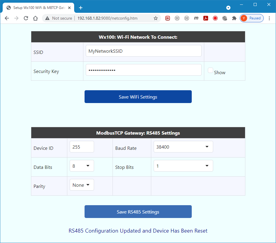
Please note that both the SSID and the Passkey are CASE-SENSITIVE you must enter in exactly the same number of characters, without any leading or trailing white spaces.
- You can now enter the SSID and the security key of the ACTUAL WiFi network that you want the device to connect to. Then click the “Save Network Settings” button to save the settings.
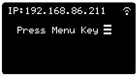
- Now turn off the DIP switch #3 and power cycle the device again. The device will now attempt to connect to the WiFi network with the SSID you entered above. If successful, the actual IP address that the device has been assigned by the WiFi network will be displayed on the OLED screen, as follow:
- If the device failed to connect to the Wi-Fi network, please check the Wi-Fi credentials and then repeat procedure 1-8 and try again. Please also check the following:
- SSID and Passkey are typically case sensitive so make sure that they have been correctly entered.
- The SSID you entered is for the 2.4GHz WiFi band only.
6. Configure RS485 For RTU#
Once you have setup the WiFi, the only other thing you need to do is to setup the RS485 communication parameters to make it work successfully as a gateway to connect RS485 based Modbus RTU devices wirelessly to the TCP/IP.
Most Modbus RTU devices can only communicate using a predefined set of “serial parameters”. These include the bit rate (aka BAUD Rate), the number of data bits (7 or 8 bits), the number of stop bits (1 or 2 bits) and the “parity” (none, odd or even). All connected Modbus RTU devices must be configured to the same set of serial parameters in order to share the same “RS485 bus”. Please refer to the device manual of each connected RTU device on how to change their serial communication parameters.
Once the set of serial parameters have been chosen, the Wx100-ModbusGW must be configured to operate on the same set of parameters. You can do this quite easily using its built-in keypad and display, allowing you to change the parameters at anytime, as follow:
a) Setup RS485 Using Keypad
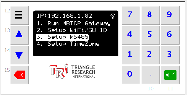
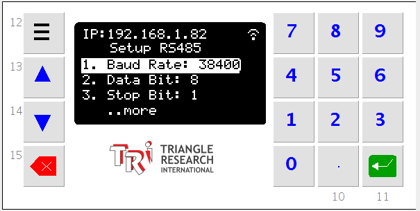
To change a parameter, press the number associated with the parameter (e.g. press 1 to change the “Baud Rate”) or press the “Up/Down” arrow key on the keypad to move the highlight bar to the parameter, then press the green “Enter” key and it will cycle through all the supported baud rates (from 2400bps to 230.4Kbps).
If you press the “4” or “5” key the menu will display the second page, allowing you to change the “Parity” as well as RTU time-out (the amount of time the gateway will wait for a response from the RTU before declaring time-out error to the Modbus TCP client).
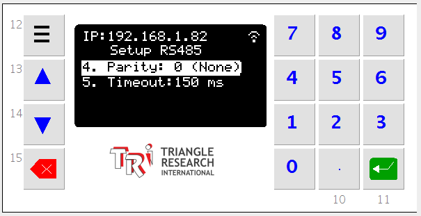
b) Setup RS485 Using PC or SmartPhone
You can also set up the RS485 using your PC or Smartphone web browser and point to its IP address and load the following web page:
http://[IP address]:9080/netconfig.htm
(please remember to always enter the port number “:9080” following the IP address)
The lower section of the above web page contains all the available selections for each parameter. For example if you click on the “Baud Rate” choice box you can select from one of the commonly supported baud rate:
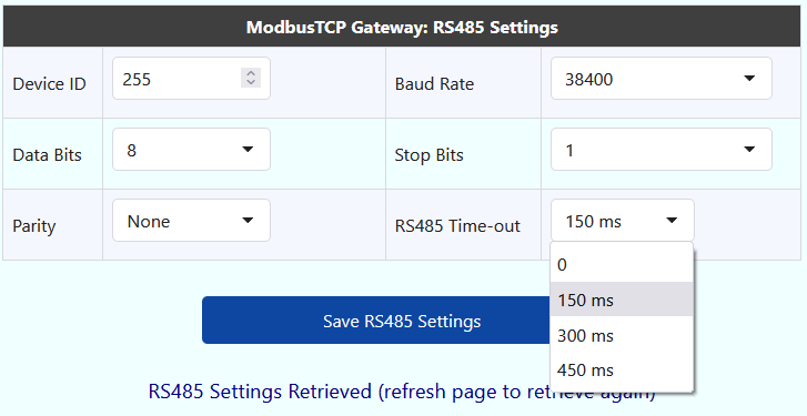
Once all the serial parameters have been defined, click “Save RS485 Settings” button to save the parameters. The changes to RS485 settings are applied immediately and reboot is not required.
c) Changing Gateway ID
The Wx100-ModbusGW possesses its own 8-bit Modbus ID that is important such that it is what determines whether a Modbus TCP command packet it receives is destined for itself (i.e. to be used for I/O read and write), or to be translated into Modbus RTU packet (i.e. to function as a gateway) as explained in Section 7 – Using Wx100-ModbusGW
The default ID for the Gateway is 255 and we recommend not changing it unless absolutely necessary. In Modbus TCP specifications, both ID=0 and ID=255 is defaulted for the gateway itself and hence must not be assigned to any slave RTU.
If for any reason you need to change the gateway ID, you can do it using either the keypad as described in a) or via the Web App as described in b).
Note:
- If the new ID you just changed happen to also be the same ID as one of the RTU devices connected to the RS485 port, then any Modbus TCP packet will no longer be routed to that slave device. In other words, the Modbus TCP client (e.g. SCADA Master) will lose communication with the RTU device but instead any read/write command will be processed by the gateway itself.
- The standard RTU broadcast command (using Modbus ID = 00) is not supported by the gateway.
7. Using Wx100-ModbusGW#
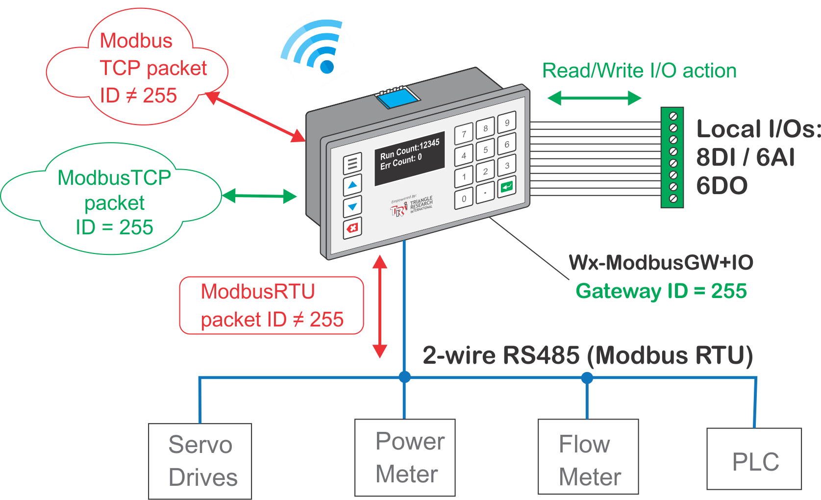
The Wx100-ModbusGW functions immediately as a Modbus-TCP to Modbus-RTU gateway and as a Modbus-TCP I/O board once the PLC is booted up and successfully connect to the WiFi network. The 8-bit Modbus ID embedded inside the Modbus TCP command packet will determine where the packet goes to eventually, as illustrated in the following diagram:
a) Using The I/O Board Function
All the ModbusTCP client need to do is to connect to port 502 (standard ModbusTCP port) of the gateway’s IP address and and start sending Modbus TCP protocol packet.
The Wx100-ModbusGW will automatically process all incoming Modbus-TCP protocol packet it receives. The gateway first examines the 8-bit Modbus ID embedded in the TCP packet. If the Modbus ID matches the Wx100-ModbusGW own ID (default is 255 decimal, or FF Hex), then it will treat the command packet as destined for its own I/O and internal registers and will respond accordingly. The client can read the device digital inputs and outputs using Modbus function 1,2,3 or 4 and write to the device digital outputs using Modbus function 5,6 or 16. This is how the client can control the I/O of the Wx100-ModbusGW device using Modbus-TCP commands.
b) Using the Modbus Gateway Function
On the other hand, if the 8-bit Modbus ID in the Modbus TCP packet that the Wx100-ModbusGW receives does not match its own ID, then it will regard the packet as being destined for Modbus RTU devices connected to its two-wire RS485 port. The device now effectively function as a gateway and it will immediately translate the ModbusTCP protocol packet into Modbus RTU packet and send out to the RS485 port.
If a Modbus RTU device that is attached to the gateway’s RS485 bus has a matching ID to the RTU command packet, it will process the RTU command packet and send back a RTU response packet. The gateway upon receiving the RTU response packet will in turn translate it into Modbus TCP protocol packet and return to the Modbus TCP client. This completes the command/response Modbus TCP protocol exchange between the Modbus TCP client and the Modbus RTU device. The process occur automatically without any further user intervention.
c) Displaying Modbus Gateway Statistics
Wx100-ModbusGW provide a simple statistics for its work as a Modbus-TCP to Modbus-RTU gateway. By pressing the MENU key on the keypad and then select “1. Run MBTCP Gateway” the OLED screen will display real time info about the number of Modbus TCP packets it receives and the number of RTU errors it encounters as shown in the following pictures:

Notes:
In normal operation, it is not necessary to display the real time statistics in order for the Wx100-ModbusGW to function as a gateway. It is provided more as a troubleshooting tool during commissioning and during maintenance.
In fact running the display continuously will consume some CPU performance as the CPU must spend time refreshing the slow graphical display, resulting in slower performance and perhaps slightly higher error rate than when it is not running the display.
To exit the display screen, press the “hamburger” MENU key.
d) Troubleshooting Gateway Error
In normal operation, if all the RTUs accessed by the Modbus TCP client are connected to the RS485 port and are working properly, then there should be very low error count (typically < 0.01%). However, if the display is showing a lot of errors then something is not right and should be rectified to ensure that the gateway performance is not compromised.
The Modbus TCP client side software should be able to report no response from a particular slave ID # and you can then investigate the RTU device with that slave ID to check for configuration errors.
The most likely causes of communication error with the RTU slave are:
- The client is trying to access a Modbus RTU slave that is not connected to the RS485 bus.
- The RTU slave’s RS485 serial port settings is incorrect and not the same as the rest of the connected devices.
- More than one RTU device connected to the same RS485 bus has the same ID, resulting in conflicting response when both devices try to respond to the same command.
- The RS485 wire to the affected RTU slave is broken.
- The RTU slave RS485 hardware is faulty.
- The RTU slave is located too far away from the gateway. Although RS485 specifications allow the bus length to be up to 1000m (4000 ft), long distance is challenging for communication at high baud rate and it may also be necessary to provide proper termination of the RS485 bus as well as deploying pull-up and pull-down resistors on the RS485 bus.
- The RS485 serial port setting of the Wx100-ModbusGW is not configured correctly (Note that this should affect communication with all the RTU slave devices and not just a single RTU)
8. I/Os Modbus Address Map#
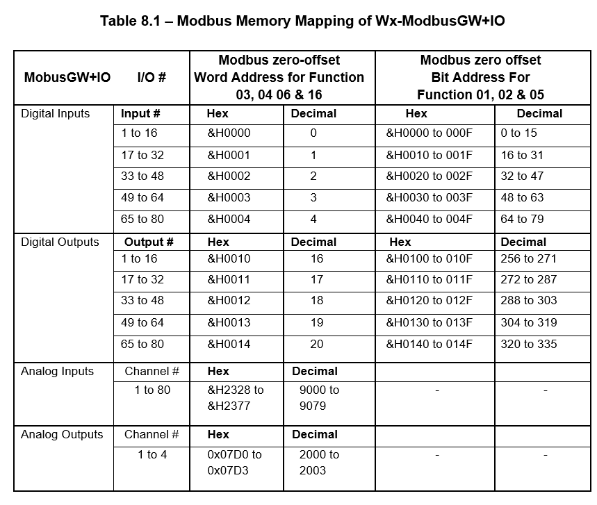
Notes:
- All I/Os are mapped to the Holding Registers as well as Input and Output Registers. Up to 16 digital input and 16 digital outputs can be read using Modbus function 03 or 04 (they are treated the same by the device). For example, the Holding Register address #0 contains the logic states of the first 16 digital inputs. The Holding Register address #16 contains the logic states of the first 16 digital outputs.
- Likewise, you can write to Holding Register address #16 to change all the digital outputs 1-16. Both Modbus function 06 (write to a single channel) and function 16 (write to multiple channels) are supported.
- The digital inputs and outputs can also be accessed as individual bits instead of as 16-bit words. The last two columns in Table 8.1 provide their respective Modbus bit addresses. So your Modbus TCP client can access any I/O bit using these addresses. Modbus function 01, 02, for bit read and function 15 for bit write are supported.
- If your SCADA program can only specify Modbus address in “Modicon” convention, you simply add 4-0001 to the zero-offset binary address in Table 8.1. For bit addresses, simply add 1-0001 to the I/Os’ zero-offset binary bit addresses shown in Table 8.1.
- The table shows mapping of up to 80 digital inputs, 80 digital outputs and 80 analog inputs. These are expanded I/Os that are available with purchase of optional expansion I/O modules. Please contact the manufacturer for more information if you require more local I/Os than is available on the basic Wx100-ModbusGW.
Appendix A - Physical Installation#
A-1 Front Panel Mount#
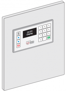
Installing Wx100-ModbusGW on the control panel front door
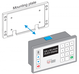
- Detach the mounting plate from the back of the Wx100-ModbusGW if it is attached there. A new Gateway may be shipped with the mounting plate loosely attached to the back of the main device body and it can be easily removed by hand without tools.However, if you find that the mounting plate has already been fastened to the back of the device using 4 screws, then remove those 4 screws to free it from the main body.
- Cut a rectangular hole of size 76mm x 47.5mm (3” x 1.87”) on the front door. Insert the Gateway from outside of the control box through the cut-out area.
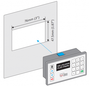
- The device should fit snugly into the cut-out area on front door. Then turn to the back of the front door.
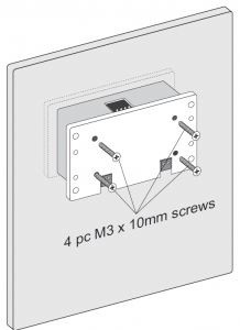
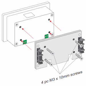
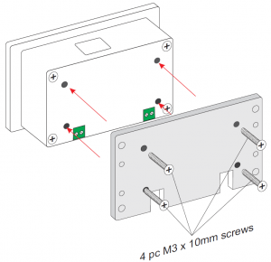
- Attach the mounting plate to the back of the Wx100-ModbusGW. Fasten it using 4 pieces of M3 x 10mm screws supplied with the package.
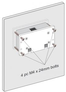
- Finally, insert the 4 pieces of M4 x 24mm bolts into the 4 larger holes on the mounting plate. Tighten the bolts to lock the device against the front door that it is mounted to.
A-2 Install On A DIN-Rail#
The Wx100-ModbusGW can also be easily installed inside a standard industrial control panel or any control boxes to prevent end-user access to the built-in HMI.
Notes:
1. If you are using a metal control panel, then please select the model Wx100-ExtA-ModbusGW, which includes a cable and an external antenna that can be installed on the external surface of the metal control panel.
2. If you are using a plastic or fiberglass control panel, then you have a choice of using either the standard Wx100-ModbusGW or the Wx100-ExtA-ModbusGW, since the plastic control panel will not weaken the WiFi signal from reaching the integrated antenna on a Wx100-ModbusGW.
You can install Wx100-ModbusGW directly on a DIN-rail using the DIN-KIT-0 as shown below. The two DIN clips that are attached to the mounting plate using 4 pcs of M3 screws included in the DIN-CLIP-SET2 allows the whole assembly to be easily snapped on to or removed from an industry standard DIN rail, as illustrated in the right-hand side picture below (without the controller to more clearly show the DIN clips in action):

Please follow the procedure listed below to assemble the DIN-CLIPs to the Wx100-ModbusGW.
- Detach the Wx Mounting plate from the back of the gateway body if it is attached there. A new Wx100-ModbusGW may be shipped with the mounting plate loosely attached to the back of its body and it can be easily removed by hand without tools. However, if you find that the mounting plate has already been fastened to the back of the device using 4 screws, then remove those 4 screws to free it from the device body.

- Attach the two DIN clips to the back of the Wx Mounting plate using 4 pieces of M3 screws (supplied with the DIN-CLIP-SET)
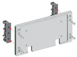
- Turn the mounting plate over and attach to the back of the Wx100-ModbusGW. Fasten the mounting plate to the device using 4pcs of M3 x 10mm screw (supplied). That completes the assembly and you can now freely clip or remove the Wx100-ModbusGW assembly from the DIN rail.
A-3 Installing External Antenna#
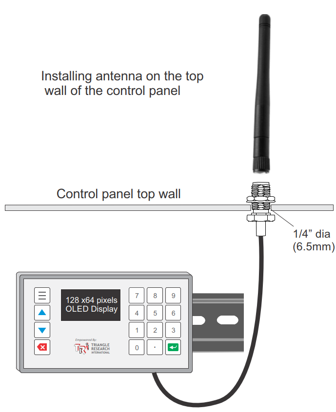
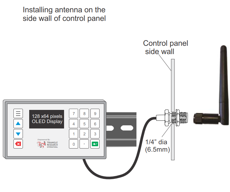
The model Wx100-ExtA-ModbusGW requires the antenna to be installed on the outer surface of the control panel. The supplied antenna can be bent from 0 to 90 degree, allowing flexible options to position the antenna.
Notes:
- Use only the antenna supplied with the device to remain compliant to the FCC/ISED/CE EMC certifications.
- If you use an alternative antenna, then you must re-certify the product to meet your local EMC standards.
- The antenna cable attached to the Wx100-ExtA-ModbusGW is about 7″ long. This means that in order to avoid adding extension antenna cable (which would attenuate the signal strength), the Wx100-ExtA-ModbusGW should be installed close to the side or the top of the control panel, as illustrated in the following two installation methods:
A-4 Direct Mounting#
Installing Wx100-ModbusGW Inside A Control Box Without DIN Rail
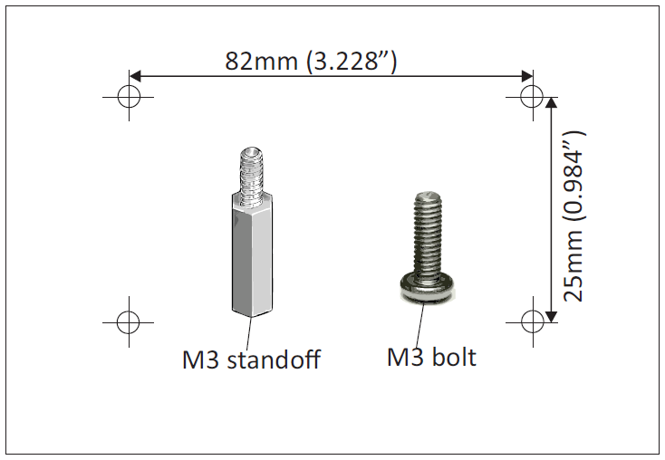
- Install four pieces of M3 standoffs, or just 4 pieces of M3 bolts inside the control box at the following locations:
- Next, attach the mounting-plate to the back of the Wx100-ModbusGW and fasten it using the 4 pieces of M3 x 10mm screws (supplied).
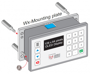
- Place the Wx100-ModbusGW over the 4 standoffs (or 4 bolts with or without spacers) and fasten each with an M3 nut as shown below.
Note:
Installing the Wx100-ModbusGW directly onto the bottom surface of the control box is the most compact form of installation as it takes up very little head space, thus allowing Wx100-ModbusGW to be deployed inside the tightest possible space. However, since the screw terminals on the device would be difficult to access after you have fastened the nuts, you should connect the required wires to the Wx100-ModbusGW power and RS485 (if used) before installing it using this method.