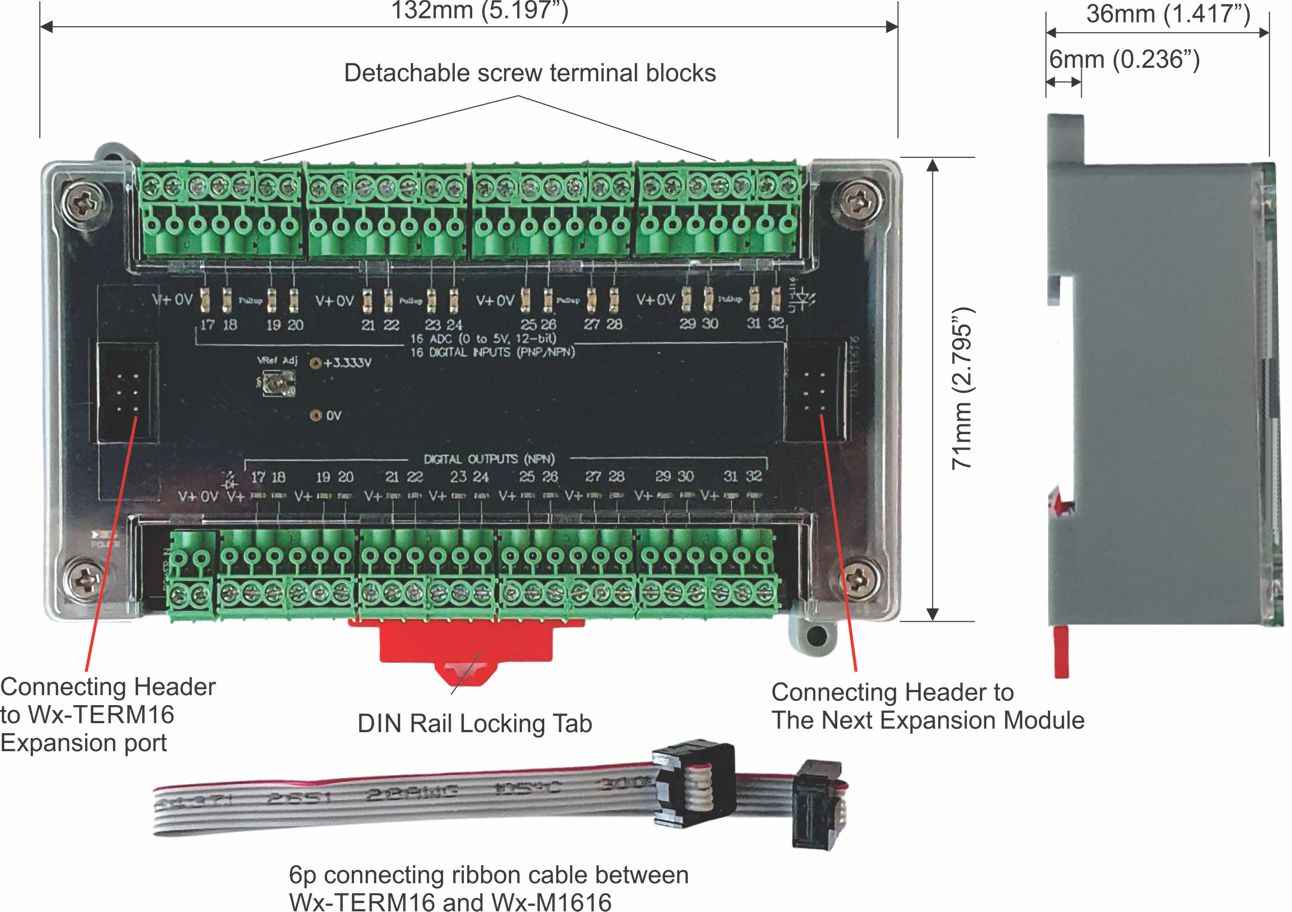
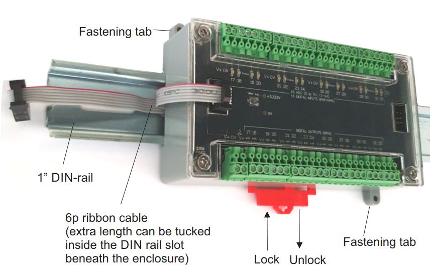
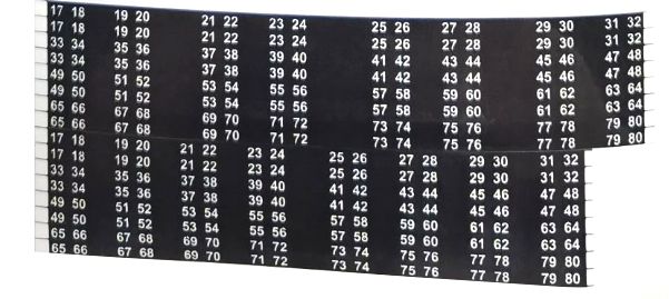
Each module of Wx-M1616 adds 16 digital/Analog inputs to the Wx100 PLC.
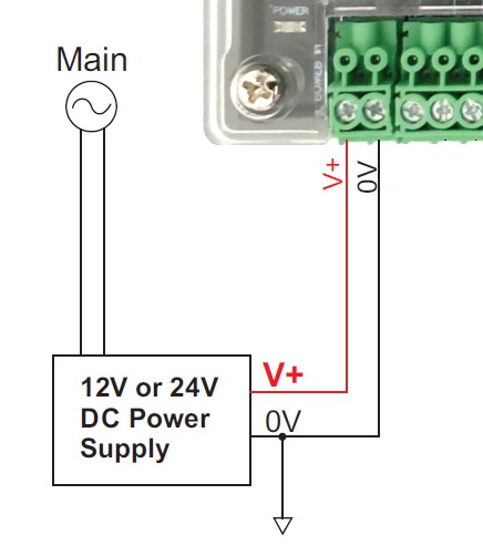
To simplify field wiring, the power input (V+ and 0V) that Wx-M1616 receives via its “POWER IN” connectors are routed by the Wx-M1616 PCB to the entire input terminal section.
a) PNP Connection
All Wx-M1616 PLC’s digital inputs are PNP (current sink) by default. This means that to turn ON the digital input you need to supply it a high positive voltage >=+8V. To turn off the digital input you need to supply it <= +3V.
| Input Voltage for Logic 0: |
Open Circuit or 0 to 3VDC |
| Input Voltage for Logic 1: |
+8V to +30VDC |
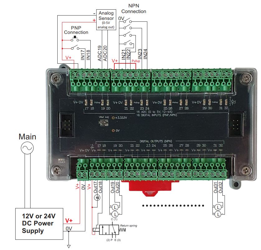
Each digital input has a green LED indicator which lights up when the input is turned ON. Connecting to a mechanical switch or push button is extremely simple – it only needs to short the V+ to the IN terminal as shown in (a) below. PNP sensors that are powered from 12 to 24V DC is just as easily connected as shown as (b) in Figure 1.5

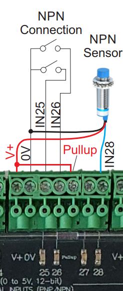
b) NPN Connection
NPN (current sink) sensors work in reverse to PNP sensors in that when it turns ON it will want to pull the input to low voltage, whereas when it turns ‘OFF’ it will either leave the input floating or pull it up to the power supply voltage level.
| By connecting the “Pullup” terminal to V+, each digital input in the group (e.g. IN17,IN18,IN19 & IN20 are in one group, IN21 to IN24 are in another group, and so on) will be pulled up to V+ via its individual internal 3.3K 0.5W pullup resistor.
This means that by default the digital input is turned ON (the green LED will light up) even if the sensor is not connected or sensor output an OFF state. When the NPN sensor turns ON it will pull the input to low, essentially turning OFF the PLC digital input. This means that the NPN sensor behaves in negative logic to the PLC.
When Pullup is connected to V+:
| Input Voltage for Inverted Logic 0: |
Open Circuit or +8V to +30V |
| Input Voltage for Inverted Logic 1: |
0V to +3V |
|
 |
Fortunately, you don’t have to think in term of negative logic when you write the PLC program. By running the special INVERT_INPUTS command once during initialization of the PLC program, you can force the PLC firmware to invert the logic of specified inputs before processing. This includes the digital I/O scan as well as all interrupt-based input functions such as pulse monitoring and high-speed counter operation:
INVERT_INPUTS ch, n
ch
|
Every 16 digital inputs are grouped into 1 channel the same way as is defined by the system variable INPUT[ch]. Wx supports up to 5 digital inputs channel = 16 x 5 = 80 digital inputs.
ch = 1: Input #1 to #16
ch = 2: Input #17 to #32
ch = 3: Input #33 to #48
ch = 4: Input #49 to #64
ch = 5: Input #65 to #80 |
| n |
bit within the channel to be inverted. Any bit that is a ‘1’ in n will signal to the firmware that the corresponding physical input bit is to be inverted during I/O scan or when it is processed by an interrupt service routine. |
E.g. If you are connecting only IN17 to IN20 to NPN sensors and the rest to PNP, that means you should set bit 0,1,2 & 3 to ‘1’ and the rest to ‘0’. So you should run this command:
INVERT_INPUTS 2, &H000F ‘ Only inputs 17 to 20 are inverted
If you are connecting first 8 Wx-M1616 inputs (IN17 to 24) to NPN sensors, then run this command:
INVERT_INPUTS 2, &H00FF ‘ Inputs 17 to 24 are all inverted. Inputs 25 to 32 are not inverted.
Note:
- Run the INVERT_INPUTS ch, n command as early as possible in your PLC program. Ideally it should be the first statement inside an INIT custom function triggered by a SCAN contact at the first rung of the ladder logic.
- An input that belongs to the input group where the “Pullup” signal is connected to V+ can no longer be configured as an analog input. Thus, if you have a system that needs to connect to analog, PNP and NPN sensors we recommend that you configure all NPN sensors to one or more groups that are pulled up.
- Although the ON/OFF input indicators on the i-TRiLOGI online monitoring screen will show correctly the input state of the input corresponding to its defined logic type (either positive or negative logic), the actual green LEDs of the digital inputs will continue to only light up in positive logic mode (i.e. when the input voltage is > 8V) even if an input has already been configured as an NPN input. This should be clearly stated in the service manual for your maintenance technicians to avoid confusion.
c) Programming Digital Inputs
All digital outputs are directly programmable in Ladder Logic as well as in TBASIC custom functions. Some programming examples are detailed in the manual:
“Wx100 PLC’s User Manual – Chapter 3 – Programming The I/Os“
