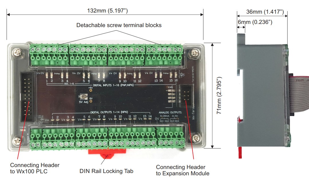
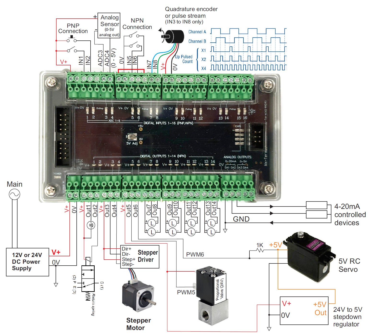
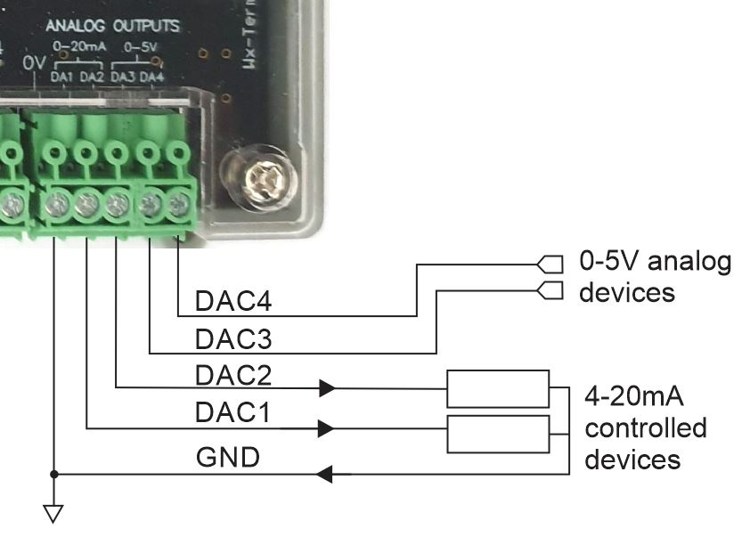
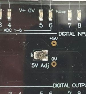
| The analog outputs on the Wx-TERM16 are referenced to the +5V regulated power supply. The 5V reference is calibrated in factory during production but can be re-adjusted using the trimmer as shown the next figure. You need to measure the voltage between the two solder pads while adjusting the trimmer when you try to re-calibrate the reference voltage. |
 |
In addition, it is possible to fine-tune each analog output channel independently by adjusting its slope and zero offset so that the output voltage or current most closely adheres to the digital value sent to the DAC.
i-TRiLOGI provides the interface so that you can save the adjustment parameters into the PLC’s non-volatile memory.
In i-TRiLOGI version 7.4, click “Controller -> Analog Calibrator” to bring up the Analog Calibrator window as follow:
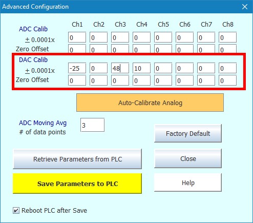
The section highlighted within the red rectangle is for calibrating the analog outputs.
a) Multiplier Factor
The fields next to the + 0.0001x are used to apply a multiplication factor to the DAC value supplied to the statement SETDAC n, value before sending it to the physical DAC output. The multiplication factor = (1+ x/10000).
For example, a statement such as SETDAC 3, 2048 is expected to supply 2048/4096*5 = 2.5V. However, if due to component tolerance you only get an output = 2.488V when the last statement was run. So the multiplication factor to “restore” the output voltage to 2.5V is (2.5000/2.488) = 1.0048. You would thus enter a value of 48 in the + 0.0001x field for DAC #3.
The formula to compute for x is thus:
x = (Expected output/Measured output - 1)*10000
For a second example, if you run SETDAC 1, 2048, the expected current output = 2048/4096*20 = 10mA. If the measured current = 10.025mA.
x = (10.0/10.025 - 1)*10000 = -25
You will thus enter the value -25 in the + 0.0001x field for DAC #3. When SETDAC 1, 2048 is run, the firmware will apply the multiplication factor to the physical analog output in order to correctly output 10mA current.
b) DAC Zero Offset
If you plot the line graph for the output voltage versus the DAC set value, the line should normally pass through the origin. But if there were any zero offset error, then the line would be above or below the origin.
The DAC output on the Wx-TERM16 should not have any zero offset error and you normally can just leave these fields set to “0”. However, if for any reason there is a need to apply a zero offset error correction, you can enter a value between –100 to +100 into the “DAC Zero Offset” field. The CPU would add the zero-offset value you enter into this field to the “X” in the “SETDAC n, x” statement and only send the sum to the actual DAC hardware.
