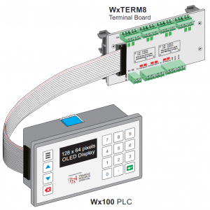
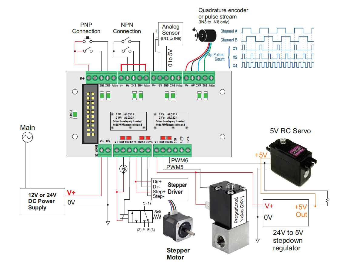
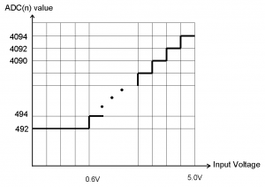
Wx100 PLC has built-in 6 channels of 12-bit, 0.6V to 5V analog inputs that is pin-shared with digital inputs 1-6.
When the PLC is first powered on input 1-6 defaults to digital inputs. Once you run a ADC(n) command the input #n becomes an analog input. The ADC(n) function returns a 12-bit analog readings from channel n. The built-in analog input is unable to properly read analog input voltage < 0.5V. Hence the range is between about 409 and 4095.
a) Wiring ADC to Wx100 PLC via Wx-TERM8 or Wx-TERM16
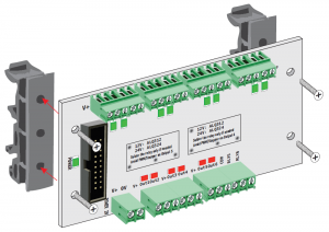
With Wx-TERM8 and Wx-TERM16, you simply wire the 0-5V output from an analog sensor directly to any of the input 1-6 and 0V to the Wx-TERM8 0V input and run the ADC(n) command to obtain the analog data.
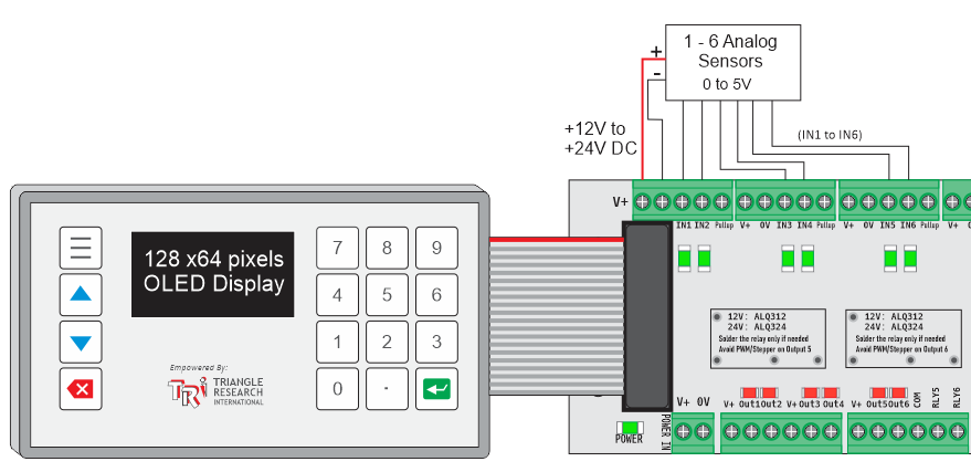
b) Wiring ADC to Wx100 PLC via Customized Terminal Board
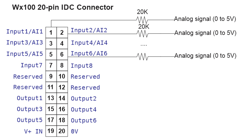
Note that each digital/analog input on a WxTERM-8 and WxTERM-16 incorporates a 20K ohm 1% current limiting resistor in between the input terminal and the signal to the Wx100 ribbon cable connector. The Wx100 has scaled the analog inputs that include the 20K ohm resistors in its calculation.
Therefore, if you design your own terminal board and have designated an input to be analog input, then you need to add a 20K ohm 1% resistor in series with the analog signal.
c) Electrical Characteristics
| No. of A/D channel |
6 |
| Resolution |
12-bit |
| Input Impedance |
164.2K ohm |
Note that each ADC input channel has an input impedance of 164.2K ohm. Hence to avoid loading effect your sensor need supply at least (5/164200 = 0.03mA) at 5V.
d) Interfacing to 0-20mA and 0-10V Analog Signals
With addition of simple resistors you can easily convert 0-20mA or 0-10V signal to 0 to 5V which can then be measured by the Wx100 analog inputs. Please refer to the following diagrams:
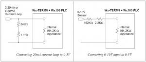
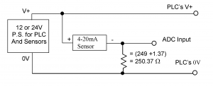
Note: The parallel resistance of the (249+1.37=250.37 ohm) and the internal 164.2K impedance of the Wx-TERM8+Wx100 PLC yields 250 ohm, which is then used to convert 20mA current to 5V.
e) Interfacing to Two-Wire 0-20mA Analog Signals
Many 4-20mA analog sensors only have two wire connections and are designed to be powered by the 4-20mA output current that flows through it. These types of sensors can be interfaced easily to the 0-5V analog inputs of the PLC as shown in the following diagram:
The sensor output will be converted to a 1-5V analog voltage and can be read by the PLC using the ADC(n) statement, which will return readings of between 820 and 4092.
